The overhaul of the tractor is inseparable from the overhaul of the clutch components. In order to improve the maintenance quality of the tractor, the overhaul methods and standards of the main components of the tractor clutch are introduced in detail.
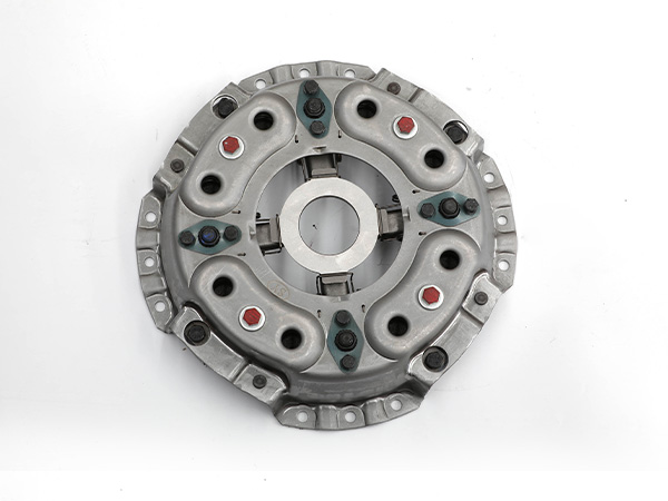
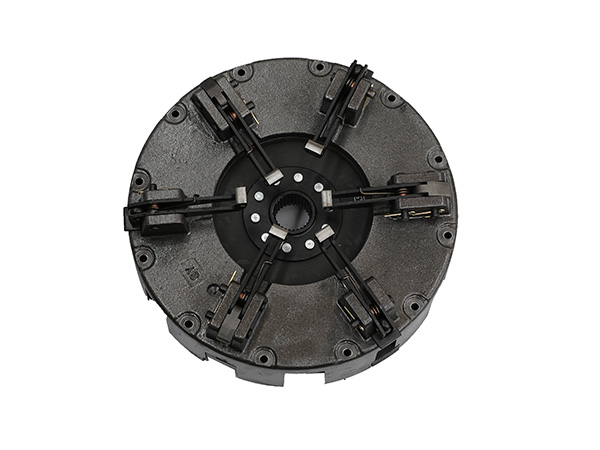
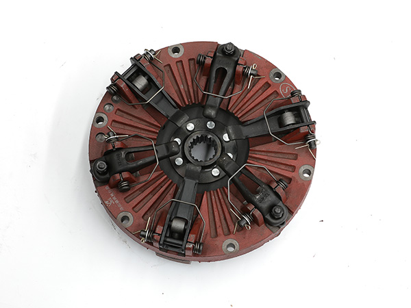
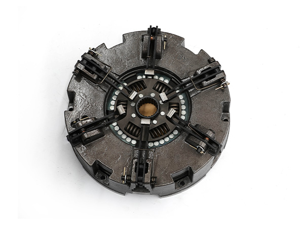
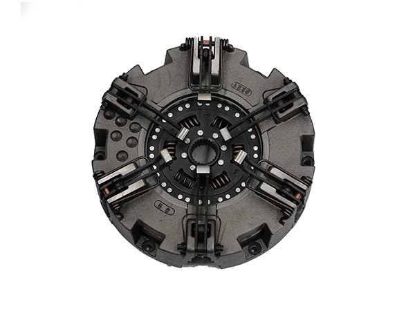
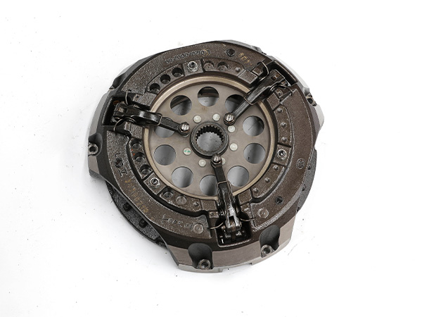
The tractor clutch is composed of four parts: the active part, the driven part, the pressing mechanism and the operating mechanism. The main component of the active part is the driving disc; the main component of the driven part refers to the driven disc with friction linings riveted on both sides; the main components of the pressing mechanism are the pressing spring, pressing lever, and pressing rod bracket; The main components are separation lever, separation bearing, etc. The following tractor clutch manufacturers talk about the maintenance of the main components of the tractor clutch based on actual experience.
Overhaul of drive and driven discs
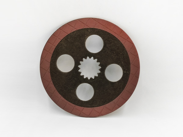
The main damage of the active disk is wear, scratches, burns and cracks on the friction surface; warpage and deformation of the friction surface. When the thickness of the active disc is 18±0.1 mm, the surface groove depth exceeds 0.50 mm, the arch deformation exceeds 0.30 mm, and the flatness tolerance exceeds 0.12 mm, it should be ground or flat. However, after polishing, its thickness is not less than 16±0.40 mm. If the active disk is cracked or too thin, it should be replaced with a new one.
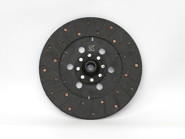
The driven disc is the most vulnerable part of the clutch. The main damage is wear, hardening, burns, cracks on the surface of the friction plate, oil stains on the surface (dry type), loose friction plate, warping and deformation of the driven disc, fracture of the steel plate, loose riveting between the steel plate and the disc, spline holes wear, etc. It can be determined by measuring the depth of the rivet head with a vernier caliper. The burial depth of the rivet head shall not be less than 0.3 mm, otherwise, use a new friction plate. If the friction plate is seriously worn or there are more than two cracks and fall off, and the burnt surface is large and deep, the new plate should be riveted again. If there is a slight oil stain on the friction plate, it can be burned off with the flame of a blowtorch, or cleaned with gasoline, and the slight burnt surface can be polished with sandpaper.
When replacing the new piece to remove the old piece, use a drill bit 0.40-0.50 mm smaller than the diameter of the old rivet to drill out the rivet head, and then gently punch out the old rivet and remove the old piece. Use a wire brush to remove dust and rust from the driven disc, and check other parts of the driven disc. The warpage of the driven disc steel plate will cause the clutch to vibrate and wear unevenly when starting, so its warpage should be checked. The warpage of the driven disc steel sheet is also called circular runout or yaw. It can be installed on the inspection frame and measured at the outermost edge of the driven disc with a dial indicator. The circular runout limit is 0.80 mm. If it exceeds the limit, it can be calibrated by cold pressing with a special clamp;
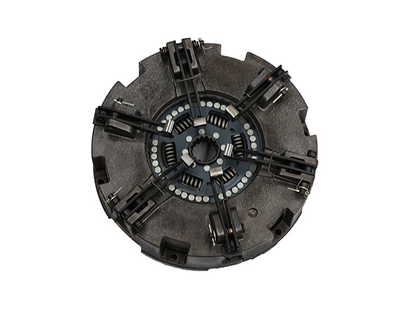
Repair of elastic push rods
The main damage of the elastic push rod is the weakening of the elastic force, the reduction of the hole center distance, the wear of the support hole, and the breakage of the elastic push rod. After the elastic force of the elastic push rod is reduced, it is heated to 780 ~ 810 ° C, quenched in oil, and then heated to 450 ~ 475 ° C for tempering.
When the center-to-center distance of the elastic push rod becomes smaller, the original center-to-center distance can be restored by thermal deformation method. between the mouth. Increase the center distance of the holes, and then perform quenching and tempering according to the above method. When the center distance of the pin holes is enlarged, care should be taken to make the center lines of the two pin holes parallel. When the fitting clearance of the pin hole of the elastic push rod is greater than 0.50 mm, it can be repaired by the maintenance dimension method. The maintenance size can be increased by 1 mm, and the fitting clearance between the pin and the hole is 0.12 mm.
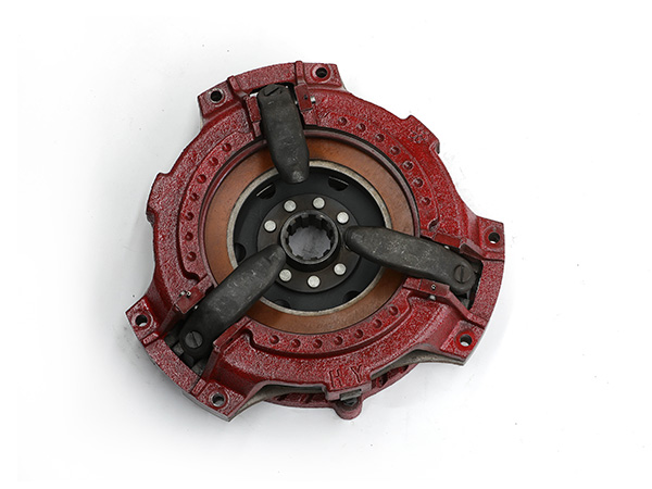
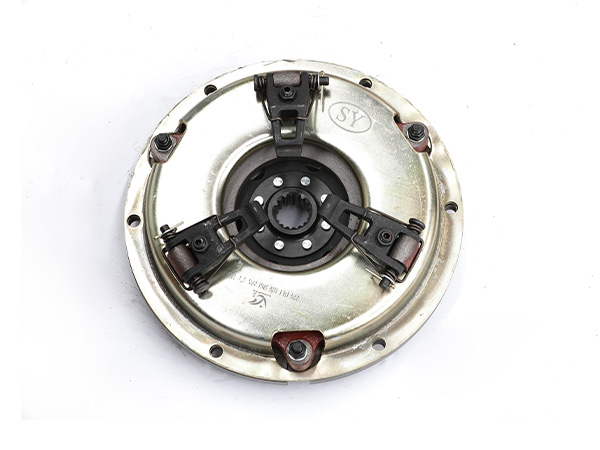
Repair of the compression lever
The pressing lever is also called pressing claw, pressing rod, cam, and releasing claw. It is commonly made of 45Cr or 40Cr; the arc hardness is HRC43-48, and the quenching depth is 1-3 mm. The main damage of the pressure rod is the wear of the pressure bearing arc surface and the pin hole. After the arc surface is worn, the distance from the bearing surface to the front hole will be shortened. The pin hole wear has a unilateral nature, the front hole is ground below, and the rear hole is ground above, which is determined by the force during compression. When the pressure rod wears less, the arc surface can be trimmed with whetstone to remove wear scars and unevenness; when the wear exceeds 1 mm, it should be repaired by surfacing welding.
Wear-resistant alloy electrodes can be used during surfacing to increase its wear resistance; after welding, use a grinding wheel to trim and form, and use a template to check the positional accuracy of the arc surface relative to the two holes, that is, use two pins to insert into the template hole and the pressure rod hole, See if the arc surfaces of the two coincide. After repair, the arc surface should be smooth and its busbar should be parallel to the center line of the two holes.
When the clearance between the pin hole of the pressure rod and the pin exceeds 0.4 mm, it should be repaired. The repair method is the same as that of the elastic push rod and carried out at the same time. It can also be repaired by inserts: the inserts are made of No. 45 steel, the wall thickness is 2-3 mm, and the interference is 0.04-0.08 mm. In addition, the pin hole can also be reprocessed after surfacing (annealing before welding), and the quality difference of each pressure rod on the same machine after repair should not exceed 15g.

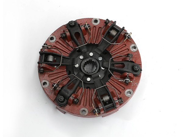
Maintenance of release bearing and release sleeve
When checking the release bearing, fix the outer ring and rotate the inner ring. If there is blockage or obvious clearance, it is because the balls and raceways are worn and should be replaced; if the rotation is flexible, but there is a slight “rustling” sound, it is due to lack of lubrication, if necessary Melt it in grease, cool it and remove it for use. The release bearing should rotate flexibly without sharp noise or jamming, its axial clearance should not exceed 0.60 mm, and the wear of the inner race should not exceed 0.30 mm. The separation bearing is closed and cannot be disassembled for cleaning or lubricant. Before loading, the bearing should be soaked in molten lubricating oil (a mixture of calcium-based grease and gear oil in half), and it can be condensed before it can be used. fitted. If it is damaged, replace it with a new one.
The main damage of the release sleeve is: the pin hole supporting the elastic push rod is worn, the front end face is worn, the hole matching the clutch bearing is worn, the interference with the release bearing disappears, and the fit with the oil seal is worn, etc. When the inner hole is worn and the fitting clearance is greater than 0.50 mm, the inner hole or journal of the sliding sleeve should be repaired according to the maintenance dimension method. When the matching parts are repaired by the insert method, the hole can be enlarged by 7 mm. In order to facilitate processing, high temperature annealing should be performed before boring.

The maintenance of the hole supporting the elastic push rod after wear is the same as the pin hole on the elastic push rod, and it is often repaired simultaneously; the treatment of the worn front end face is the same as the end face of the pressure rod bracket, and it is also repaired by the surfacing method; and the separation bearing and oil seal After the mating part is worn, it can be repaired by brush plating. The normally engaged clutch release sleeve is also known as the release bearing seat. When the trunnion fitting clearance is greater than 1.50 mm, it can be repaired by surfacing welding and brush plating, or the old trunnion can be cut off and drilled at the old trunnion. Tapping, screwing a new trunnion, and welding it firmly at the root. After repair, the coaxiality error of the left and right trunnions and the vertical error of the left and right trunnions and the sliding hole should not exceed 0.30 mm. When there is wear scar on the working surface of the ear arm of the separating bearing seat, it can be repaired with oil stone, and it can be repaired by welding when the wear is serious.
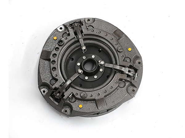
Repair of release housing and release ring
The main damage of the very engaging clutch release bearing and bearing seat is the loose fit with the bearing, and the increased fit between the two pins of the release ring. When the clearance of the former is greater than 0.05 mm, brush plating should be used to repair the mating surface and restore the fit; when the clearance of the latter is greater than 0.50 mm, the hole should be trimmed and then the oversized pin should be replaced to restore the fit (the standard clearance is 0.50 mm). 07 to 0.31 mm). After the ball head of the release ring is worn out, it can be replaced with a new ball head. The clearance between the ball head and the release ring is 0.10 to 0.42 mm, and the clearance between the ball head and the fixed seat cover is 0.14 to 0.42 mm. After wear, the pins matched with the split inner lever can be repaired by brushing or inserting.
The above is all about the maintenance of the main components of the tractor clutch. As long as the main components are regularly repaired, the service life of the clutch can be improved.