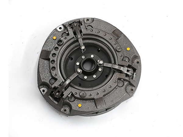
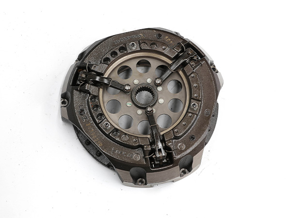
At present, the clutch assemblies installed in most 600-804 series tractors are frequently engaged, single-plate, dry double-acting clutches, but the internal structure is different. The compression deformation of the single disc spring is generated, while the pressure of the clutch disc assembly in other models is generated by the compression deformation of 12 cylindrical coil springs. Their usage and adjustment requirements are basically the same.
The use of tractor clutch operating mechanism
1. When disengaging the clutch, quickly step on the clutch pedal to the position where the front driven plate assembly is completely separated to avoid difficulty in shifting.
2. When the clutch is engaged, the clutch pedal should be slowly released at the beginning to ensure that the tractor starts smoothly. After the tractor starts, the foot stepping on the pedal should leave the pedal quickly to prevent the clutch from slipping.
3. It is not allowed to use the method of semi-coupling clutch to reduce the running speed of the tractor. Do not keep your foot on the clutch pedal while driving to avoid accelerated wear of the release bearing, pressure plate and friction lining.
4. When the tractor is parked, it should be in neutral gear, and the clutch should not be disengaged for too long.
5. When disengaging the power take-off clutch, the driver only needs to step on the clutch pedal to the end.
Tractor clutch adjustment
1. Adjustment of the free travel of the clutch pedal
In order to ensure the normal operation of the clutch, the clearance between the end of the clutch release lever and the thrust bearing end face of the release slip sleeve assembly must be kept within the range of (2.5±0.5) mm, corresponding to the free stroke of the clutch pedal of 20mm─ 30mm. In the process of use, due to the constant wear of the clutch friction plate, the pressure plate moves forward, and the gap gradually decreases or even disappears. Therefore, it must be checked regularly. There are two ways to adjust the free travel of the clutch pedal:
(1) External adjustment: Loosen the lock nut on the tie rod, remove the connecting pin, unscrew the adjusting fork, make the free stroke of the pedal reach 20mm─30mm, then insert the connecting pin, lock it with a split pin, and tighten the locking nut .
(2) Internal adjustment: Remove the cotter pin on the adjusting nut from the front inspection hole on the left side of the clutch housing, and unscrew the adjusting nut so that the clearance between the end of the loose lever and the end face of the loose sliding sleeve thrust bearing reaches (2.5 ±0.5) mm, then insert a new cotter pin and lock it. When using this method to adjust, it must be ensured that the three loose lever ends are in the same vertical plane, and the thickness should be checked with a thickness gauge, and the error should not be greater than 0.3mm.
2. Adjustment of clutch release stroke
In order to ensure the complete separation of the main clutch and the power take-off clutch, the clearance between the end faces of the three gear pins and the end faces of the three support bolts must be kept at (2.25±0.5) mm. The separation of the clutch and the PTO clutch is not complete, therefore, it must be checked regularly and adjusted if necessary.
When adjusting, screw the three support bolts until they stand against the end faces of the corresponding three gear pins, and then return the support bolts to 9 slots respectively (9 sounds can be heard), the gap is the value specified above.
3. Adjustment of the release lever position
When reinstalling the clutch disc assembly, the distance from the end of the lever to the end face of the rear driven disc assembly must be 40─0.3mm, and this value is 42.5mm when using a butterfly spring.
The above is about the use and adjustment of the tractor clutch lever mechanism. If you encounter various problems during use, please feel free to discuss with us.

