The clutch is a major assembly in the tractor drive train. When the tractor starts, the high-speed rotating engine is smoothly connected with the stationary drive train through the friction between the active part and the driven part of the clutch to ensure the vehicle starts smoothly. In the long-term use of tractor clutches, the wear and tear of parts is unavoidable, and the replacement of parts has become the main work of clutch repair. The quality of assembly and adjustment technology after parts replacement determines the service life of the clutch after repair. Next, we will mainly take a certain brand of 25 type tractor clutch as an example to introduce the assembly and adjustment points of single-plate dry clutch.
Tractor clutch assembly
1. Assembly of release bearing assembly
The clutch release bearing is installed between the clutch and the transmission, and the release bearing seat is installed on the tubular extension of the first shaft bearing cover of the transmission. The shoulder of the release bearing always touches the release fork through the return spring and retreats to the final position. Keep a clearance of 2.5 mm from the release lever. There should be an interference of 0.03 mm when the separation bearing seat is installed. During installation, the inner cavity of the bearing and bearing seat should be filled with butter, and there is no place for oiling the bearing at ordinary times.
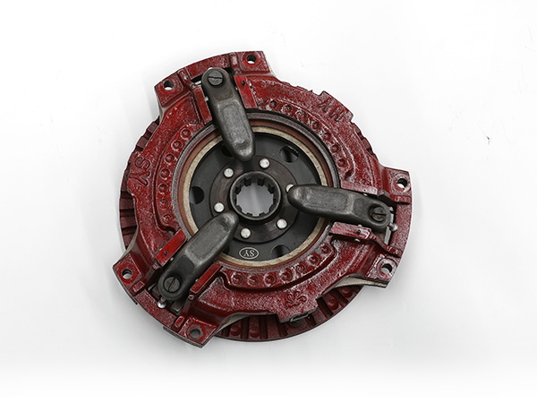
2. Assembly of clutch pressure plate assembly
The assembly of the clutch pressure plate assembly is to assemble the pressure plate, spring, clutch cover and separation mechanism together, and the spring must be compressed before proceeding. The spring can be pressurized by means of mechanical pressurization or hydraulic pressurization by self-made simple support, and also can be pressurized on a radial drilling machine.
(1) Put the pressure plate on the platform, and place a circular backing plate with a thickness of 10 mm and an outer diameter slightly smaller than the diameter of the pressure plate under the pressure plate, or place three small nuts of the same thickness on it.
(2) Place the swing block, release lever, release lever adjustment screw and pin on the inner side of the boss of the pressure plate in sequence, put the spring on the boss of the cross-shaped spring seat, and align the clutch cover with the transmission plate in place Put it on the spring, make the 4 adjusting screws pass through the corresponding holes on the clutch cover, and straighten the transmission plate so that the unriveted end is aligned with the screw hole on the pressure plate.
(3) Pressurize the spring on the clutch cover, and compress the spring by more than 10 mm. At this time, screw on the adjusting nuts one by one, and then fix the transmission disc bolts together with the transmission disc bolt seats in the screw holes of the pressure plate, and punch riveting Bolt seat.
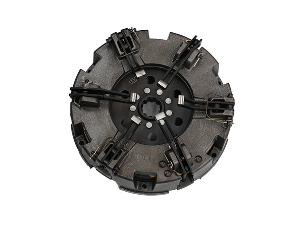
3. Installation of driven plate assembly and pressure plate assembly on the flywheel
This installation is mainly about the centering of the driven disc assembly, so during installation, the clutch shaft (namely the first shaft) can be used as the mandrel, or an optical shaft can be used instead. Insert the center of the driven disc with the optical shaft, insert it into the flywheel bearing hole, then install the pressure plate assembly to the plane of the flywheel, and tighten it diagonally with six M8×20 bolts. With the optical shaft pulled out, the center of the driven disc is correctly fixed on the flywheel.
Post-installation adjustment of tractor clutch
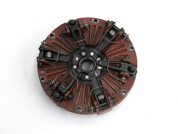
1. Adjustment of separation lever
The heights of the working surfaces at the inner ends of each separation lever of the clutch must be consistent, that is, the working surfaces at the inner ends of each separation lever must be in the same plane parallel to the end surface of the flywheel. At the same time, the height of the working surface at the inner end of the release lever should also comply with the original manufacturer’s regulations, otherwise, during the process of clutch separation and engagement, the pressure plate will be skewed and the separation distance will be insufficient, resulting in incomplete separation and vibration when the vehicle starts . The structure of the clutch is different, and the adjustment of the release lever is also different.
There are currently 3 common types:
① Rotate the adjusting nut at the outer end of the separation lever;
② Rotate the adjustment nut in the middle (fulcrum) of the separation lever;
③Turn the adjusting screw at the inner end of the separation lever. When the adjusting nut is screwed in, the inner end of the separation lever is adjusted up, otherwise it is lowered. Adjusting screws are mainly used to make the end faces of each adjusting screw in the same plane. When the screws are screwed in, the end faces are adjusted down, otherwise they are adjusted up. When the adjustment meets the requirements, the adjustment screw (or nut) must be locked.
2. Adjustment of clutch pedal free travel
After the parts of the clutch control mechanism are assembled, adjust the spherical adjustment nut to change the length of the release rod, so that the release bearing can move back and forth on the release sleeve. The distance between the end face of the release bearing and the working face of the end of the release lever is reflected on the clutch pedal as the free travel, and the free travel of the pedal is required to be 30×40 mm. If it is too large, screw in the spherical adjusting nut; otherwise, screw out the spherical adjusting nut, and then tighten the lock nut.
(1) When adjusting the free travel, generally the distance between the release bearing and the release lever should be about 1.5 mm, and a pedal free travel of 30-40 mm can be obtained, which can be checked with a thickness gauge or a special plug.
(2) After the separation lever height (35.4±0.20) mm is adjusted, the height cannot be lowered arbitrarily to adapt to the free stroke of the pedal. journey.
(3) If you feel that the free travel of the pedal is too small during use, it is generally caused by the increase in the height of the separation lever end after the friction plate is worn thin. If the clutch is working normally at this time, you can adjust the free travel of the pedal through the spherical adjustment nut . If the clutch does not work normally and the free stroke decreases, the small flywheel housing can be removed, and the release lever adjustment nuts can be adjusted one by one to make the gap between the end face of the release lever and the release bearing the same, and the normal pedal free travel can be restored.
Note that when checking the free stroke of the pedal, first check whether the pedal returns to its position. If the pedal return spring is too soft, the pedal cannot be reliably returned, and the return spring should be replaced.
The above is all about the clutch assembly and adjustment methods, aiming to improve the repair quality of tractor clutches, and hope to help everyone better.

